Bench Supply (Start 9-4-11)
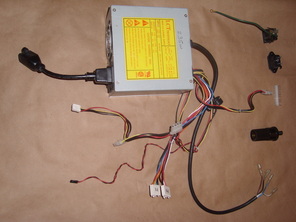
Fig 1. Basic Parts to start
This is the Realtime project bench Power Supply using old Computer power supplies as a base. The cost savings is enormous. Every one needs a bench supply for the many electrical things in the home even if they are light weight techs just playing around. Want to plug in an Automotive device with only a fat 12volt Cigarette Lighter connection? Need to charge several batteries at a time? Need a serious short protected heavy current lab like supply? We can do it all and on the cheap.
The pictured (Fig 1) supply is a PC AT supply from many years ago. Notice the 2 white connectors at center bottom labeled P8 and P9? Those plugged into the PC Mother board. The black connector on the left is the Monitor power plug that was often used then to turn the monitor on with the computer. It makes a handy power plug on the bench that can be controlled with the bench supply. In the lower right is the 4 leads that connect to the power switch (both hot and return where switched).
Any working PC supply probably can be used but it may be prudent to use fairly recent ones so as to have ready access to replacement parts. In this case I plan to make the bench supply out of an unmodified AT Supply plus lots of old parts "added on" including a case from a newer supply as a container and junction box. To the right in Fig 1 are some possible add on parts such as a 3 prong AC receptacle and HP AC connector that may be useful on the bench of computer people (like me). Also a 12 volt receptacle for Car stuff so you can test things on the bench. Then there is a connector removed from an old PCAT so I could just plug in the supply instead of cutting off the wires and hard wiring them into the supply. This allows me to recover a working PCAT supply and use it if needed some day. Ic can easily be replaced with a newer supply with minor mods as needed.
Parts collected so far
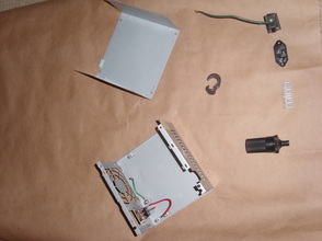
The parts of an old PCAT power supply case are to be used shown in Fig 2 along with the other small parts collected so far. The nice thing about this project is it is so flexible. You can ad on or modify it for a large number of purposes as there are only a few requirements to safety and operability, which I aim to cover.
This empty case has a working power switch we can use to turn on the Bench Supply Which I may start calling PS for power supply. I plan to put the "strain relief" around many of the wires comming out of the old PS and rout them into the empty PS case, thus eliminating a bunch of wires hanging out and giving a place to secure some terminals and such.
Note that I will leave on 4 pin connector to dangle free so I have external access to a power connector for floppies, Hard disk drives and such on the bench with no further work. I also happen to have a 5 volt and return line with a berg connector. No particular use but it is done and there so leave it accessible.
I have several PC PS cases both good and bad. I keep the bad ones for the many useful parts such as fans, cases, switches, caps, heat sinks, coils, large diodes, lots of wires, etc. The working ones can become supplies for other projects too. These supplies from the start were far superior to older non switching supplies. Low heat loss, very high regulation, high current draw, good isolation from line noise and efficient. I remember may a power sag or light flicker that would kill my old Radio Shak or S100 computer but the PC-AT and newer just road through fine. I bought a lot of filters for the older computers to little avail.
Quasi Schematic, 9-23-11
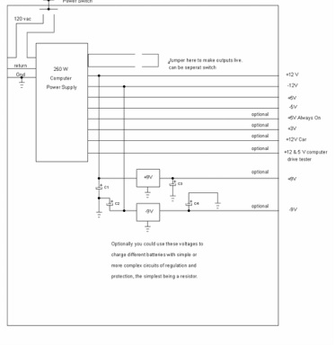
This is the general layout of the PS with several options to select from. You could of course add any you feel you need. The connections on the right could be wires sticking out, screw terminals, jacks or any other way you want to connect. Be sure to keep leads short or at Caps near the ends of long leads to reduce noise and loading.
I plan to use jacks for plugging in a meter as well as screw terminal block for basic hookup. I had thought I might have 1 or 2 dedicated multi-meters for voltage and even current measure but I decided I could hook the meters on anytime. It might be better to put a break out in each line to measure current so I will think about that.
Using this as a battery charger seems like a bonus use but some thought needs to be given to limiting current and voltage to the batteries. For example, 2 AA or AAA batteries could be hooked in series to the 3 volt supply if a series resistor limiting the current were used. The current would be that which the batt manufacturer recommends as safe. This would definitely not be quick charging.
1-31-12
An added feature that could come in handy in today's "Green" conscious world is a way to measure power use. Since power is just the current times the voltage, we just need to measure both at the same time. That takes 2 multimeter's then to get the readings (of course you could measure one and then the other if the device is a pretty constant load). Measuring the voltage is simple (and left to the student as an exercise), but to measure the current one needs to intercept it. That means we need a way to divert the flow of current to the DUT (device under test) with out interupting it. We do that with a switch that routes the current through the multimeter current measurement. So we measure the voltage and then put the multimeter in the current mode and switch it in to measure the current. Multiply the 2 and we have the power used at that moment.
Of course we would need to also consider the worst case and steady state loads so we would need to configure the DUT to these conditions before measuring. It is a good idea to keep a note book of tests and measurements for future reference (like trouble shooting a degrading operation, say). One simple way to do this is put 2 connection points for the meter and a switch between them. Thus, conceptually, we have the circuit representing the real world right there. Connect the 2 current probes and then open the switch and the current must flow through the meter. Close the switch and then measure the voltage. Cost, 2 terminals, a small switch and some work.
