Quick and Dirty PICAXE Microcontroller Serial Port Tester
This is a fast tool for testing weather the comm port is working. It can be reprogrammed in minutes. There is no faster prototyping than using the PICAXE pre-programmed micro-controller that has BASIC built in and cost less than $10 including shipping, software and working MPU. You must make a serial cable using 2 resistors. I will have a write up on programming the PICAXE soon in the beginners or workbench pages. Here I will assume you know how to program your PTCAXE. We will use a PICAXE8M 8 pin chip for this project. The code Is pretty short, see below. And the schematic is just dirt simple. MPU, cable, 5 resisters, LED, cap and battery ads here ......
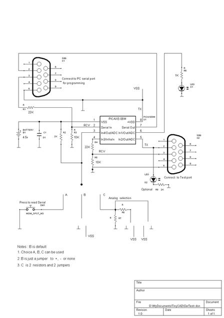 The schematic is full up populated but in reality you can compromise or delete many parts. The serial connectors can be left out and hard wired to cables. The LED could be left off if you are connected to a PC with a Term program or the PICAXE editor (debug). The LED could be moved to other in or outputs. Many changes are possible to the program or hardware as the need arises. I left the switch off and just move a jumper wire from gnd to power, as needed. I don't use the pull up resistor either. That is the point of this project. Adaptability. that is the goal.
To use it, close or jumper the switch/jumper to GND, then you can watch the optional LED as it will go 3 seconds if there is a serial input. The output is a steady 3 bytes incrementing up the ASCII code of alphabet and numbers. You can put anything you want there, in the code and recompile. Takes only seconds. You may need to turn off (unplug) power if the reprogram wont catch. Just hit the program button and immediately power on and it will usually program. One note of caution. This circuit does not use the MAX 232 power converter chip (too expensive for me) so it works on most PCs but will not work on true RS232 devices without some conversion to plus and minus voltages. And if you did use the MAX232 chip, be sure to reverse the polarity in the code by changing the n2400 speed setting to t2400 for True 232 polarity. This would only be necessary on the tester side as the PC side for programming is looking to find the direct input with no MAX circuit. |
Code for the tester in PICAXE BASIC #com6 ;Serial Tester Set com port #
#picaxe 08M ;could possibly use 14M or 20M with pin change b4=0 ;set b4=0 and use for real serial input at GOSUB sin ;output 1, realpin 6, LED ;output 2, realpin 5, serial output line ;input 3, realpin 4, serial input test pin ;input 4, realpin 3, "button"/jumper real test serial on=1 main: high 0 ;LED off, output 0, realpin6 let b1=46: b2 =b1 + 1: b3=b1 + 2 ;start at char = "012" looop: wait 3 ;must wait to see LED let b1=b1 + 3: b2=b1 + 1: b3=b1 + 2 serout 2,n2400,(b1,b2,b3);realpin 5, out 3 bytes steadily debug ;test if alive, not needed if b1 > 121 then let b1 = 46 ;out bytes 30 to 121, repeat end if if pin4=1 then gosub sin ;go chk serin if inp3=1, could hang goto looop ;repeat ;subroutines sin: serin 3,n2400,b4;test for real serial in(will hang till data) serout 2,n2400,("Byte=",b4," ");realpin5, send out the input high 1 ;LED (realpin6) on to show it got Data wait 3 ;wait long enough to see LED is on low 1 ;LED (realpin6) off return ;be sure to turn off button or keep sending serial ;The optional resistor R8 is used to watch input into the tester ;from your test device. I allows a limited amount of Stand-Alone ;testing, no need for a PC. Note that you could connect only the ;output of the device and not feed it chars from the tester. |
